How to find timer clock frequency and its time period with crystal frequencies
- 12 MHz
- Divide by 12 = 1 MHz ⇒ This is clock frequency
- Reciprocate: 1/1M = 1 μs ⇒ This is clock time period
- 16 MHz
- Clock Freq = 16/12 = 1.333 MHz
- Clock Time Period = 1/1.333M = 0.75 μs
- 11.0592 MHz - standard xtal frequency
- Clock freq = 11.0592/12 = 921.6 kHz
- Clock time period = 1/921.6k = 1.085 μs
Counter
- Used to count the number of events
- Counts pulses from Tx input pin (T0 or T1)
- P3.4 for Counter 0, P3.5 for Counter 1
Usage
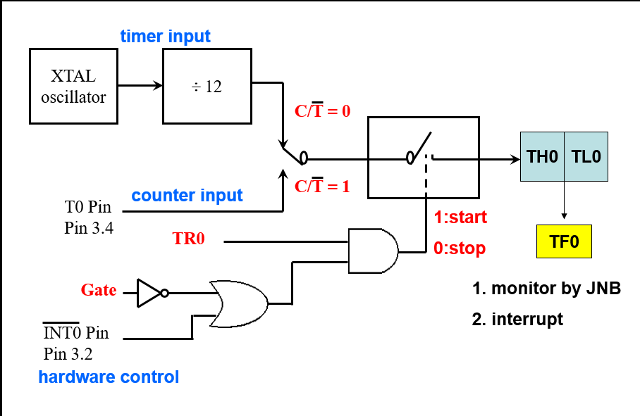
Timer/Counter 0
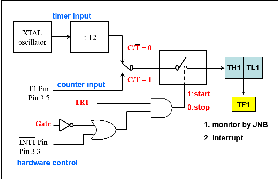
Timer/Counter 1
Registers used in Timer/Counter
- TH0 TL0 for timer 0
- TH1 TL1 for timer 1
- TMOD for timer mode
- TCON for timer control
Timer 0 and 1 registers (16 bits)
- These are 16 bits wide (TH and TL combined)
- Can be accessed separately using TH and TL (high byte and low byte)
- Used to store the time delay in timer mode
- The number of events in counter mode
TCON register (8 bits)
- Upper nibble used for timer/counter, lower nibble is used for interrupts
- Bit addressable, you could just set a single bit to whatever you want
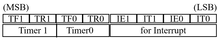
- TR bits (Run Control Bits)
- Used to turn the timer/counter on/off
- TF bits (Timer flag, control flag)
- This is like carry. It is originally 0. When TH-TL roll over to 0000 from FFFFH (basically overflow) the TFx bits are set to 1.
- If interrupt is enabled, this TFx will trigger ISR.
Equivalent instructions to set the Timer Control register
For Timer 0
| Specific bit | Bit Addressable |
|---|
SETB TR0 | SETB TCON.4 |
CLR TR0 | CLR TCON.4 |
SETB TF0 | SETB TCON.5 |
CLR TF0 | CLR TCON.5 |
For Timer 1
| Specific bit | Bit Addressable |
|---|
SETB TR1 | SETB TCON.6 |
CLR TR1 | CLR TCON.6 |
SETB TF1 | SETB TCON.7 |
CLR TF1 | CLR TCON.7 |
TMOD Register
- This is an 8 bit register
- Lower nibble (4 bits) for timer 0
- Higher nibble (4 bits) for timer 1
- NOT BIT ADDRESSABLE
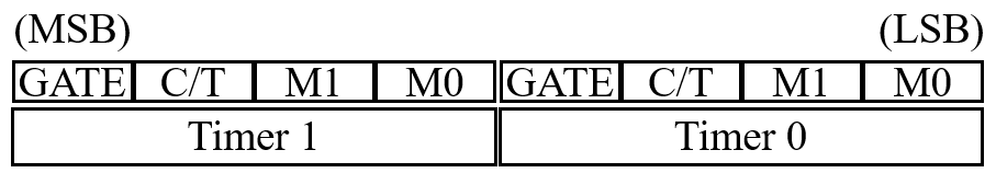
GATE
- Gating control when set.
- Enables an external control over the timer
C/T
- Select timer mode or counter mode for the operation
- Timer mode is 0 and it takes the clock input from the crystal (used to generate delay)
- Counter mode is 1 and it takes the input from INTx (used to count events)
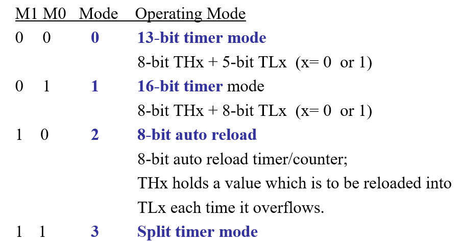
M0 and M1
- Mode bits which help to set the mode of the timer
Time delay calculation
- To create a time delay of a set amount of time, the THx and TLx of the timer must be set to a specific amount which we need to calculate.
- The TMOD of that timer should be set to mode 1 timer x with
MOV TMOD #01H
- The TFx has to be wiped to monitor:
CLR TF0
- To start the timer you must set TRx:
SETB TR0
To find the timer values
- Divide desired time delay with time period of the clock cycle (usually 1.085μs). This will give you a value.
- Subtract this value from 65536, you will get another value
- Convert this value to hexadecimal
- Load first half into THx and second half into TLx
MOV TMOD, #01
HERE: MOV TL0, #0F2H
MOV TH0, #0FFH
CPL P1.5
ACALL DELAY
SJMP HERE
DELAY: SETB TR0
AGAIN: JNB TF0, AGAIN
CLR TR0
CLR TF0
RET